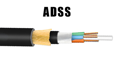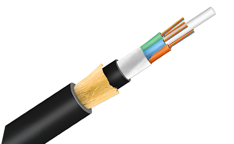

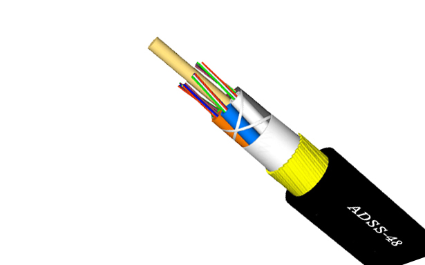
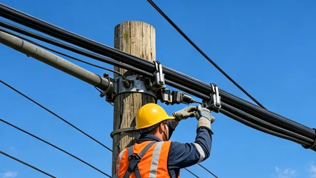
ADSS-S Single Jacket All-Dielectric Self-Supporting Aerial Fiber Optic Cable
Power-free installation
Lightweight and small diameter can reduce the load on cable towers and struts due to freezing and wind.
Large span, the maximum span can reach more than 1000m
Good tensile and temperature resistance
Long lifespan, up to 30 years or more
what is adss-s fiber optic cable
ADSS-S fiber optic cable is an all-dielectric self-supporting single-jacket aerial cable built with loose-tube stranded fibers and aramid yarn strength members under a PE (or anti-track) outer sheath, enabling long-span, power-free installation directly on overhead power transmission lines.
ADSS-S Fiber Optic Cable Specification
- Specification
- Product Technical Parameters
- OPTICAL CHARACTERISTICS
optical properties
| G.652 | G.655 | 50/125μm | 62.5/125μm | |
|---|---|---|---|---|
| Attenuation (+20℃) | ≤3.0 dB/km @850nm | ≤3.0 dB/km @850nm | ||
| ≤1.0 dB/km @1300nm | ≤1.0 dB/km @1300nm | |||
| ≤0.36 dB/km @1310nm | ≤0.40 dB/km @1310nm | |||
| ≤0.22 dB/km @1550nm | ≤0.23 dB/km @1550nm | |||
| Bandwidth (Class A) | ≥500 MHz·km @850nm | ≥200 MHz·km @850nm | ||
| ≥1000 MHz·km @1300nm | ≥600 MHz·km @1300nm | |||
| Numerical Aperture | 0.200±0.015NA | 0.275±0.015NA | ||
| Cable Cut-off Wavelength | ≤1260nm | ≤1480nm | ||
| Storage/Operating temperature | -40℃ ~ +70℃ | |||
Technical parameters
| Out Diameter (mm) | Fiber cores | Daily max working tension (KN) | Max working tension (KN) | Break Strength (KN) | Strength Member CSA (mm²) | Modulus of Elasticity (N·k/mm²) | Heat Expansion Coefficient (×10⁻⁸/K) | Suitable Span (m) | ||||
|---|---|---|---|---|---|---|---|---|---|---|---|---|
| PE sheath | AT sheath | A | B | C | D | |||||||
| 12.5 | 125 | 136 | 1.5 | 4 | 10 | 4.6 | 7.6 | 1.8 | 160 | 100 | 140 | 100 |
| 13.0 | 132 | 142 | 2.25 | 6 | 15 | 7.6 | 8.3 | 1.5 | 230 | 150 | 200 | 150 |
| 13.3 | 137 | 148 | 3 | 8 | 20 | 10.35 | 9.45 | 1.3 | 300 | 200 | 290 | 200 |
| 13.6 | 145 | 156 | 3.6 | 10 | 24 | 13.8 | 10.8 | 1.2 | 370 | 250 | 350 | 250 |
| 13.8 | 147 | 159 | 4.5 | 12 | 30 | 14.3 | 11.8 | 1.0 | 420 | 290 | 400 | 280 |
| 14.5 | 164 | 177 | 5.4 | 15 | 36 | 18.4 | 13.6 | 0.9 | 480 | 320 | 460 | 320 |
| 15.1 | 179 | 193 | 7.95 | 22 | 53 | 26.4 | 18 | 0.3 | 670 | 460 | 650 | 460 |
| 15.6 | 194 | 208 | 10.5 | 28 | 70 | 33 | 19.6 | 0.1 | 800 | 560 | 800 | 560 |
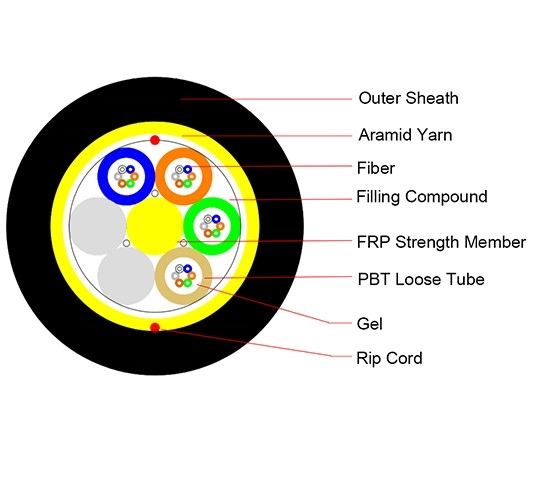
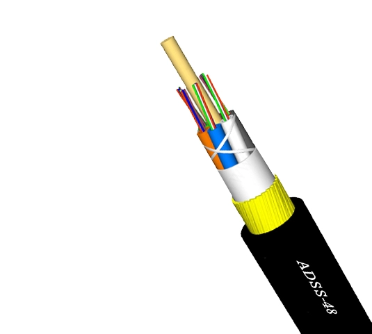
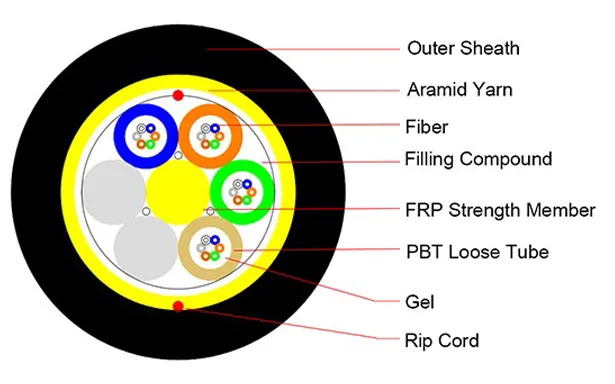
Product Structure & Composition
Complete cable structure (from outside to inside):
Outer Sheath – Protects the entire cable from environmental and mechanical stresses.
Aramid Yarn – Provides tensile strength and acts as a rodent deterrent.
Rip Cord – Allows easy removal of the outer sheath without tools.
FRP Strength Member – Fiber Reinforced Plastic rod that offers rigidity and anti-buckling strength.
PBT Loose Tube – Polybutylene terephthalate tube that houses the optical fibers loosely.
Gel – Water‑blocking gel that prevents moisture ingress inside the loose tube.
Fiber – The optical glass fiber that transmits light signals.
Filling Compound – Additional filler (often a thixotropic compound) that surrounds the fiber and blocks water.
ADSS-S Fiber Optic Cable Product Features
Extra‑long span capability
Maximum span can exceed 1.000 m.
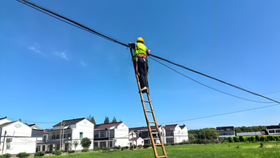
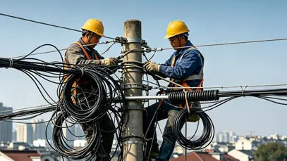
Power‑free installation
No electrical power required during deployment.
Lightweight & small diameter
Reduces load on cable towers and struts caused by freezing and wind.
High durability
Excellent tensile strength and temperature resistance, with a service life of 30 years or more.
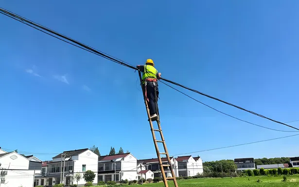
Engineering Applications ADSS-S Fiber Optic Cable
Power Communication Backbone for High-Voltage Lines
ADSS-S cable is used on 110kV–500kV transmission lines to carry dispatching automation, relay protection, and real‑time monitoring. Its all‑dielectric design eliminates EMI and lightning risks, ensuring stable low‑latency transmission.
With low fiber attenuation and high bandwidth (10Gbps+), it connects substations and control centers without needing separate rights‑of‑way.
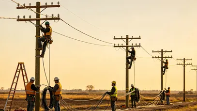
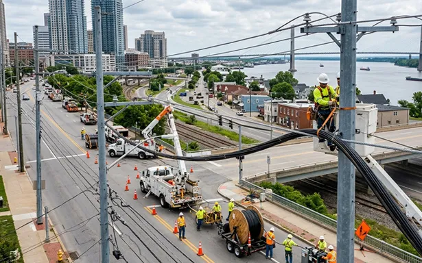
Long‑Span Deployment Over Complex Terrain
Self‑supporting and lightweight, ADSS-S achieves spans up to 1,500–1,800 meters – ideal for river crossings, mountain valleys, and long transmission corridors.
It resists wind (150+ km/h), ice, UV, and temperatures from -40°C to +70°C, making it reliable in coastal, high‑altitude, and harsh environments where metallic cables corrode.
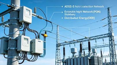
Distribution Automation & Smart Grid
ADSS-S enables real‑time backhaul for distribution networks (<35kV), supporting advanced metering, reclosers, and switchgear using existing utility poles.
Passive optical network (PON) architectures allow point‑to‑multipoint connectivity, optimizing fiber usage for substations, feeder terminals, and DER monitoring.
Aging Line Retrofit & Live‑Line Installation
With no metallic parts, ADSS-S can be installed on live lines without power outages – saving up to 40% construction time and 30% cost compared to traditional methods.
It attaches directly to existing towers or poles without structural modifications. For voltages >35kV, an anti‑tracking (AT) jacket prevents dry band arcing, ensuring long‑term safety.
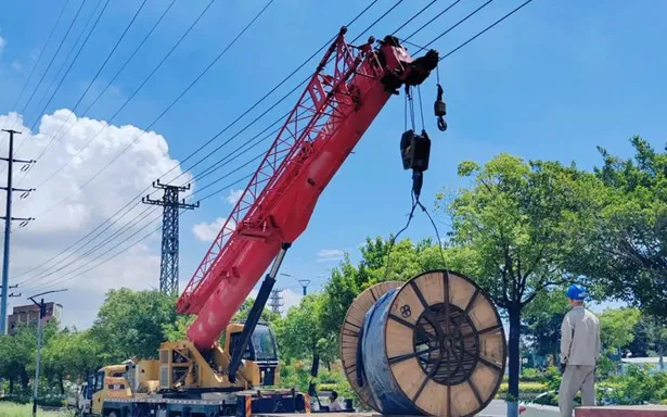
Shipping & Packaging
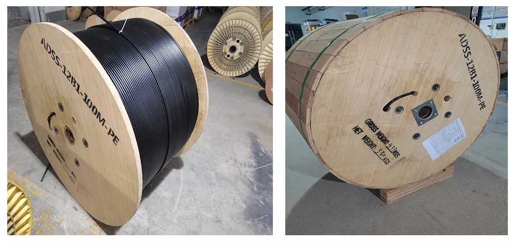
Packaging Requirements:
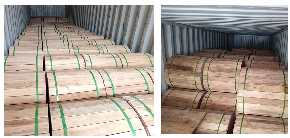
1:All cables shall be wound on treated wooden spools that are not returnable
2:Cable ends must be firmly secured to the spool and protected with waterproof shrink caps
3:Each spool must include:
Protective plastic wrapping layer
Reinforcing wooden slats for stability
Minimum 1m of free cable end for testing purposes
Standard spool length: 3000mm (±2% tolerance allowed)
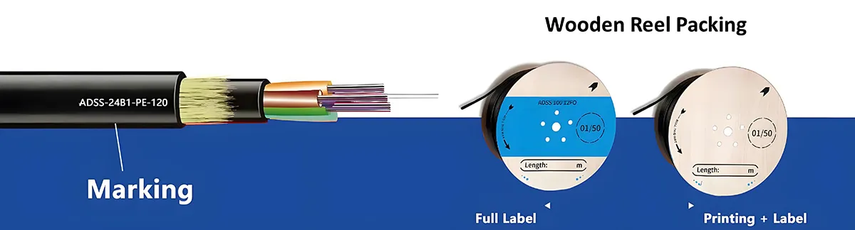
Cable Identification:
The outer jacket must display:
1、Unique sequential numbering every 1m (±1% variance permitted)
2、 Additional repeating markings at 1m intervals showing:
Product code and fiber count
Manufacturer identification
Production date (month/year)
Total cable length
Standard Packaging Dimensions:
| Length | Container | Size (L×W×H) | Net Mass | Total Mass |
|---|---|---|---|---|
| 2 km | Wood spool | 90×75×90 cm | 156 kg | 220 kg |
| 3 km | Wood spool | 100×68×100 cm | 240 kg | 280 kg |
| 4 km | Wood spool | 109×75×109 cm | 300 kg | 368 kg |
| 5 km | Wood spool | 129×72×129 cm | 400 kg | 480 kg |
Technical Reference:
1、 Standard cable diameter: 10.0mm
2、Maximum span distance: 100m
3、Contact sales team for complete technical specifications
Spool Marking Standards:
Permanent markings (minimum 25-30mm height) must appear on both sides of each spool:
1、 Company name and trademark
2、Contained cable length
3、Cable specifications (type/fiber count)
4、Winding orientation
5、Weight measurements (gross/net)
Note: All wooden packaging materials must undergo proper fumigation treatment prior to use.
Product Comparison:
ADSS-S (Single Sheath ADSS) VS ADSS-DS (Double Sheath ADSS) VS Figure-8 (Figure-8 Self-Supporting) VS OPGW (Optical Ground Wire)
| Feature / Dimension | ADSS-S | ADSS-DS | Figure-8 (Self-Supporting) | OPGW |
|---|---|---|---|---|
| Laying Distance (Max. span) | 80–150 m (can reach ~200 m with optimization) | 200–400 m (can exceed 1000 m with high aramid content) | 100–500 m (but >300 m may cause excessive sag) | Up to 1000 m+ (very long crossing spans) |
| Structural Features | Single PE/AT (Anti-Tracking) outer sheath; aramid yarn as primary strength member; loose tube gel-filled/filled-free design; all-dielectric (non-metallic). | Double sheath (inner + outer PE/AT); double layer of aramid yarn for enhanced tensile strength; all-dielectric construction with additional mechanical protection. | “8” shaped cross-section with integrated steel messenger wire; metallic core; optical fibers housed separately from supporting steel strand. | Steel/aluminum tube containing optical fibers stranded with Al-clad steel and/or aluminum alloy wires; dual-function: grounding + communication. |
| Typical Applications | Medium voltage (≤110 kV) power lines; short to medium spans (80 m–150 m); urban/rural distribution networks; FTTH backbone in mild environments. | High voltage (≥110 kV) power lines; long spans (200 m–400 m+); harsh weather regions (rivers, valleys, heavy wind/ice zones); highways crossing. | Short span aerial deployment (<500 m); telecom/general purpose; rural broadband; budget‑sensitive projects with mild climate; no high‑voltage interference. | Extra-high voltage (220 kV+) transmission lines; new construction or ground wire replacement; backbone power grid; areas requiring high lightning/shield performance. |
| Pros in Engineering | Lightweight, low wind/ice load; easy one-step installation; no grounding required; cost-effective for medium voltage; excellent corrosion immunity; AT jacket available for tracking resistance. | Superior mechanical strength for long spans; enhanced UV/weather resistance; dual sheath for extra durability; minimal electrical tracking risk; excellent dielectric protection. | Simple and fast installation (no separate messenger); low initial cost; widely available hardware; integrated steel strand eliminates extra supporting wire. | Dual functionality (grounding + communication); extremely high tensile strength (up to 150 kN+); excellent lightning/short-circuit withstand; long span capability (>500 m). |
| Cons in Engineering | Limited span (<150 m); PE jacket unsuitable for HV lines (>110 kV); requires careful sag/tension design; AT jacket adds cost for higher voltage use. | Heavier and larger diameter; higher upfront cost; more complex installation planning; requires precise hardware matching; higher material consumption. | Cannot be used near HV lines due to metallic messenger (EMI/electrical hazards); steel strand prone to corrosion; heavier weight per km (~300 kg/km); shorter lifespan (~15 yrs). | Metallic structure requires proper grounding; higher initial investment; complex installation (must match line design); difficult for retrofitting existing lines without ground wire replacement. |
| Cost (Relative) | Lowest among ADSS family. e.g., 24‑core for 100m span ~$0.25‑0.35/m; AT jacket adds 15‑25%. | Higher than ADSS-S. Additional aramid + outer jacket increase material cost; long‑span design (500m) 24‑core up to $0.90‑1.20/m. | Low initial cost (about 0.8‑1.2 USD/m for common spec), but higher long‑term TCO (maintenance and earlier replacement). | Highest. For 24‑core, market price typically $0.70‑1.40/m; specialized engineering increases overall project budget significantly. |
| Maintenance Difficulty | Low. No corrosion/rust; periodic visual inspection; regular cleaning needed in polluted areas; quick damage repair; minimal specialized tools. | Low to Medium. Extra sheath reduces environmental wear; internal inspection harder; more aramid means more complex re‑tensioning; otherwise similar to ADSS-S. | Medium. Steel strand needs rust protection and grounding checks; higher repair complexity; potential messenger separation issues; sag monitoring required. | Medium. Requires periodic ground resistance/continuity testing; harder to access fiber core; specialized joint hardware and trained personnel needed. |
| Span Capability (typical) | 80 m–150 m; up to ~200 m with optimization; designed for medium loads. | 200 m–400 m; can exceed 800 m with high aramid content; handles heavy wind/ice. | 100 m–500 m, but >300 m may cause excessive sag; integrated steel strand. | Up to 1000 m+; extremely robust for long crossing spans (rivers, canyons). |
| Voltage Compatibility | ≤110 kV (PE jacket); AT jacket extends to higher voltages (≥110 kV) but single sheath limits extreme HV use. | ≥110 kV, suitable for up to 220 kV+; widely used in EHV lines; double jacket reduces electrical tracking. | Not recommended near power lines (>1 kV); metallic components cause safety hazards and EMI. | ≥220 kV; standard for UHV/EHV; integrated as shield wire. |
| Lifespan / Durability | 25+ years (AT jacket extends life in HV environment). | 30+ years; double sheath adds abrasion/UV protection. | ~15 years (steel corrosion and fatigue). | 30+ years (metallic parts require corrosion care). |
| Environmental Suitability | Coastal, mild, industrial (with AT jacket); standard UV protection; good for medium wind/ice. | Extreme weather, high UV, heavy ice/wind zones, high salinity; excellent for challenging terrains. | Mild climates, low corrosion risk; not suitable for coastal or high‑humidity areas without coating. | Any terrain, but needs proper grounding; excellent lightning/short-circuit performance. |
ADSS-S Fiber Optic Cable Selection Guide
ADSS-S Fiber optic cable Installation (Short Version)
1. Plan & Inspect: Survey route, check voltage level (≤110kV for PE sheath; ≥110kV needs AT sheath). Inspect cable reels and hardware. Perform OTDR pre-test.
2. Hardware Mounting: Install suspension clamps 1–2m below phase conductors. Use proper sheaves (min. 12″ diameter). Add vibration dampers for spans >100m.
3. Stringing: Place reel on stand with brake. Pull via pulling grip and swivel, tension ≤20% of RBS. Maintain communication between operators.
4. Sag & Clamp: Adjust sag using laser (follow sag‑tension table). Install permanent suspension/dead‑end hardware.
5. Finalize: Waterproof splice points. Perform OTDR acceptance test (≤0.25 dB/km @1550nm). Keep bending radius ≥30× cable OD during pull, ≥10× after.
Download YRTFIBER Product Catalog
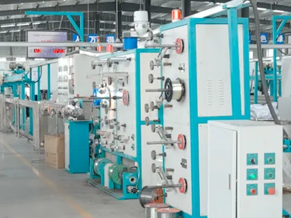
Factory Real Shot
Complete optical cable production line
We have a complete optical cable production line with an annual output of over 100.000 kilometers of optical cable.
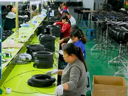
Skilled workers
The factory has a team of skilled workers, and this stable workforce ensures our product quality and delivery capabilities.
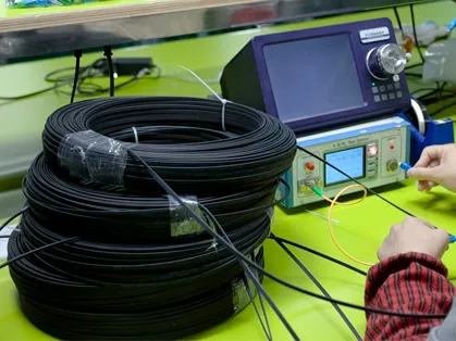
Quality Control Laboratory
Routine tests include tensile strength, crush resistance, temperature cycling, and water penetration to ensure compliance with industry standards.
Final Coiling & Packaging Zone
Finished cables are precisely coiled onto wooden or steel reels, wrapped with protective materials, and labeled for shipment.

Frequently Asked Questions & Quick Inquiry
ADSS-S Fiber Optic Cable FAQ
1. What is an ADSS single jacket fiber optic cable?
ADSS (All-Dielectric Self-Supporting) single jacket cable is a lightweight aerial fiber optic cable that requires no metallic support. It is designed for easy installation along power poles and utility routes without needing a messenger wire.
2. What fiber types and core counts are supported?
The cable supports 2 to 288 fiber cores, using standard single-mode fibers such as G.652D and G.655. This makes it suitable for a wide range of applications from access to backbone networks.
3. What is the maximum span this cable supports?
This specific model is designed for aerial spans up to 150 meters, depending on environmental conditions and installation requirements.
4. Is the cable resistant to environmental stress?
Yes. The cable’s structure includes a water-blocking gel-filled loose tube, aramid yarn strength members for tensile support, and a durable outer jacket that offers excellent resistance to UV, moisture, temperature variations, and mechanical stress.
5. What are common applications of this ADSS cable?
ADSS cables are widely used in:
FTTH (Fiber to the Home) rollouts
Power line communication networks
Rural broadband deployment
Backbone fiber optic links in utility corridors
Send Your Inquiry
Fill out the form below and we'll get back to you within 24 hours.